Welcome,
I am a Mechatronics Engineer driven by continuous learning, innovation, and efficiency. The following projects showcase my hands-on involvement at every stage — reflecting my passion for engineering, my problem-solving mindset, and my ability to create meaningful results with limited resources.
Erasmus+ Internship Project
Improvements & Revision for a Master Thesis Project: "Friction Modelling of Pneumatic Cylinders for Servo-Positioning Systems" at Politecnico di Torino
IMECH-2
My Mechatronics Engineering Bachelor Degree’s thesis: "Design & Development of a Back-Drivable 3 DoF Parallel Manipulator"
Ultrasonic-Based Autonomous Mobile Robot
Designed and developed a modular autonomous ground vehicle capable of navigating and avoiding obstacles using ultrasonic sensors. Responsible for the complete mechanical architecture, CAD design, manufacturing, assembly, design validation, technical documentation, and production-oriented engineering deliverables.
PixelFlight
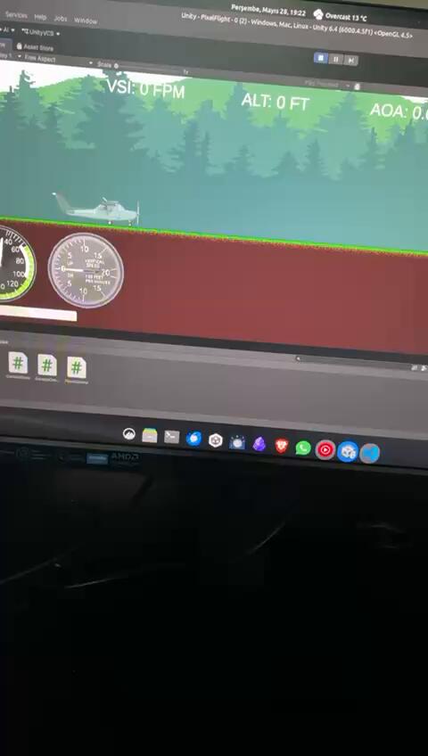
2D Flight Simulation that I developed in Unity as side personel project.
Orientation Prediction with IMU
My R&D Internship Project Development: "Obtaining Orientation Data with Sensor Fusion"
Real-Time Control of 2-DoF Robotic Arm
My Real-Time Control lecture project, Real-Time Control of 2 DoF Robotic Arm
PID Control Project
PID Control Lecture Project: "PID Position Control of a DC Motor"
Ultrasonic-Based Autonomous Mobile Robot
Tasks: Design and manufacture the complete mechanical system of an autonomous obstacle avoidance vehicle. Develop a modular and maintainable platform capable of integrating electronic subsystems while ensuring structural reliability, manufacturability, and future scalability for serial production.
WP-1: Mechanical Architecture & Concept DevelopmentDefined the vehicle architecture, chassis layout, wheel configuration, bearing selection, and component placement strategy. Evaluated design alternatives considering manufacturability, structural stability, ease of assembly, and maintenance requirements.
WP-2: CAD Design & Mechanical IntegrationDeveloped all mechanical components and assemblies using CAD software. Integrated motors, ultrasonic sensors, control electronics, bearings, and fastening elements into a compact and structurally robust platform while ensuring accessibility for maintenance and future modifications.
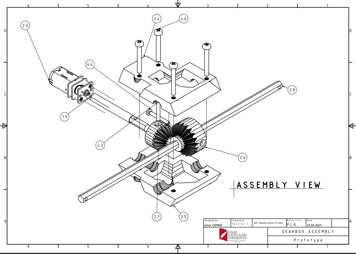
WP-3: Manufacturing & AssemblyManaged the production and assembly process of all mechanical components. Coordinated prototype manufacturing, verified dimensional compatibility of parts, and performed complete system assembly.
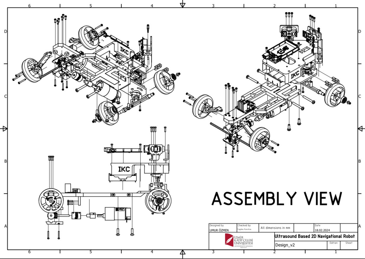
WP-4: Prototype Validation & Design ImprovementsConducted post-manufacturing inspections and identified mechanical issues during testing. Redesigned and optimized components where necessary to improve structural integrity, assembly efficiency, and overall system reliability.
WP-5: Engineering Documentation & ProductizationPrepared complete technical drawings, CAD file structures, assembly documentation, and manufacturing packages. Created a Bill of Materials (BOM) to support procurement, inventory management, and future production activities.
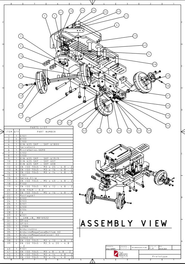
WP-6: Project Coordination & Technical ReportingPresented weekly project progress, design decisions, encountered challenges, and implemented solutions during interdisciplinary team meetings. Maintained technical documentation throughout the project lifecycle.
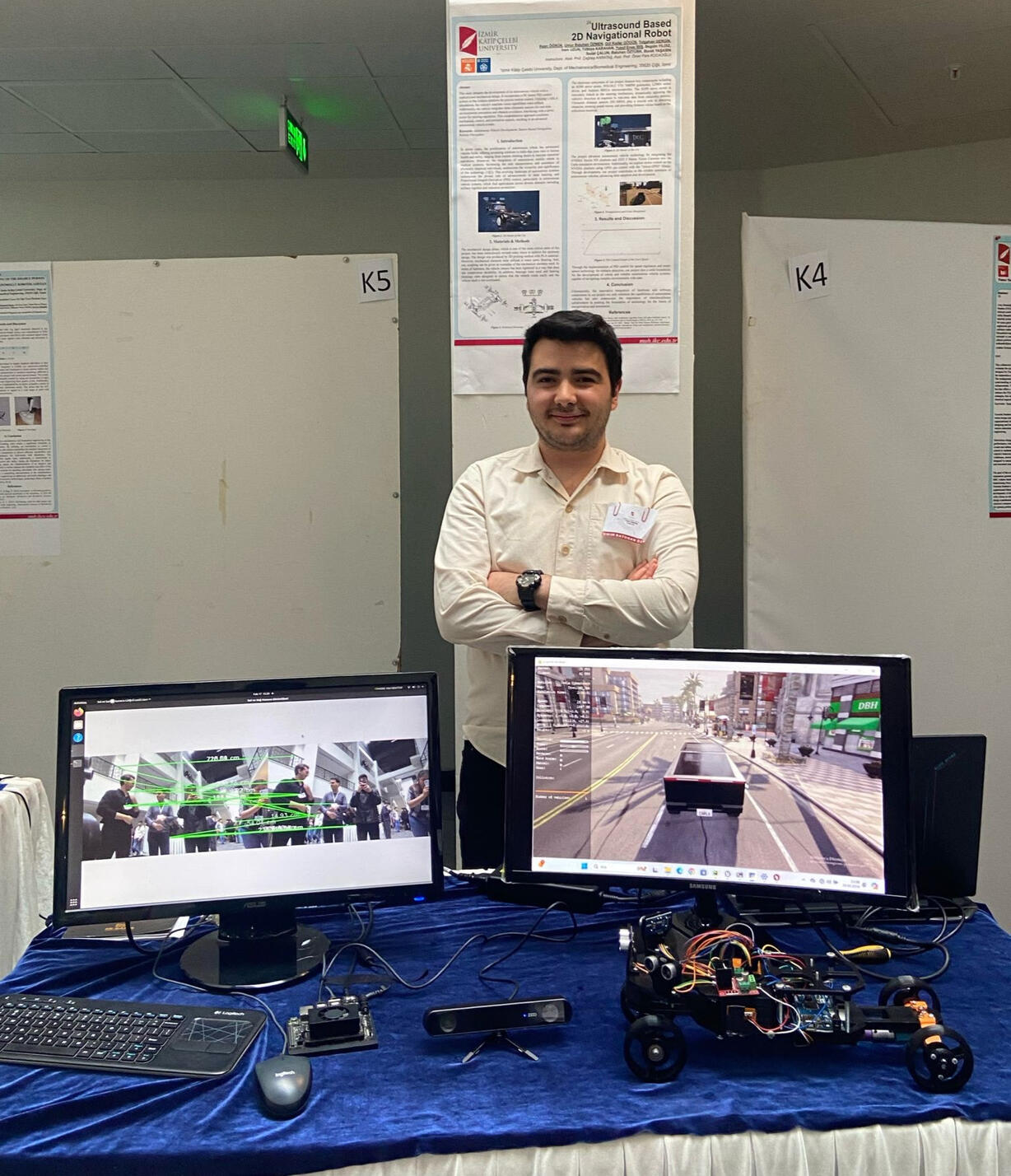
Results: A fully functional autonomous obstacle avoidance vehicle was successfully developed and validated. The mechanical system provided reliable operation while supporting seamless integration of sensing and control subsystems.The final design featured a modular architecture that enabled rapid maintenance, straightforward component replacement, and future upgrades. Complete engineering documentation, manufacturing drawings, CAD datasets, and BOM records were delivered, establishing a foundation suitable for repeatable manufacturing and further product development.
PixelFlight: 2D Flight Simulator
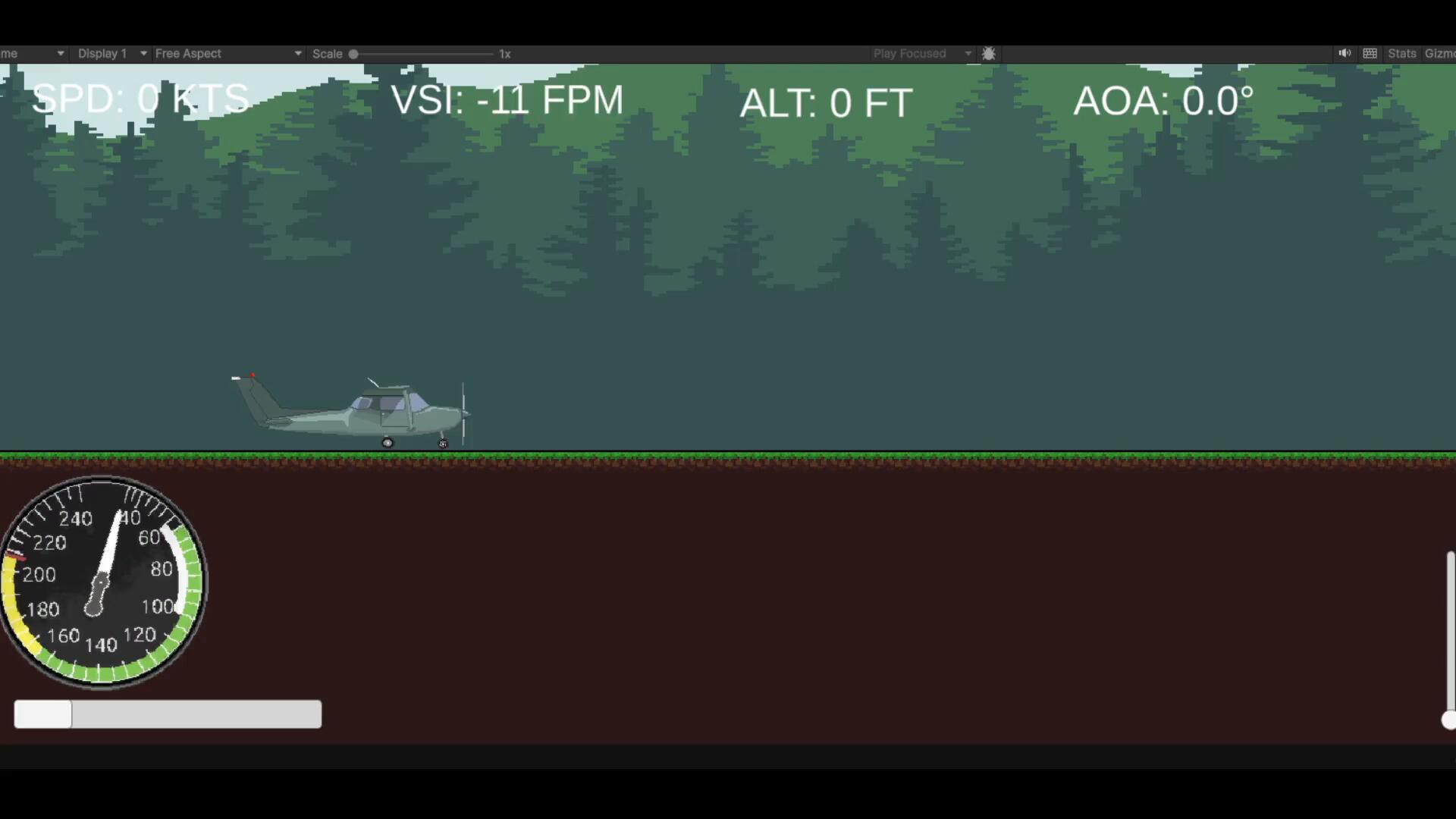
In PixelFlight—a side project I developed out of my interest in aviation and airplanes—my goal was to observe how realistic flight would look in a 2D environment by applying real aerodynamic formulas and flight principles while simplifying them as little as possible. To achieve this, I began by conducting research. I adapted the information I gathered from my research to my own project and used the following physics system.
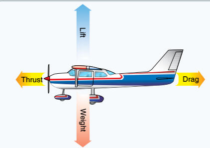
Essentially, balanced and stable flight occurs when the sum of the four distinct forces shown above is zero. Within the scope of this project, modeling and simulating these four forces in the Unity environment forms the core of the physics mechanics. However, situations may also arise—such as during takeoff and landing—where these four forces are not equal. For this reason, concepts such as AOA (Angle of Attack) and pitch angle are also taken into account, and a Free Body Diagram (FBD) can be drawn as shown below.
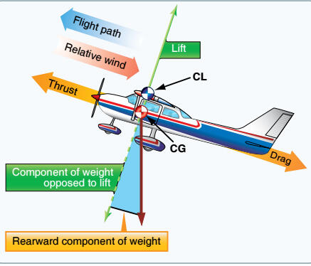
Here, CL refers to the Center of Lift, and CG refers to the Center of Mass. While the CG is already defined in the Unity program and can be automatically defined and adjusted due to the RigidBody2D property, the position of the CL was determined by creating an empty Game Object. These forces are examined one by one below.
1. Lift Force
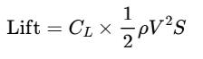
In the formula above, C and ρ are variable coefficients. The CL coefficient is known as the lift coefficient; it is dimensionless, and a formula adapted for its calculation is provided.

Here, α represents AOA. This nonlinear coefficient, which is generally based on experimental results, was plotted based on the graph below.
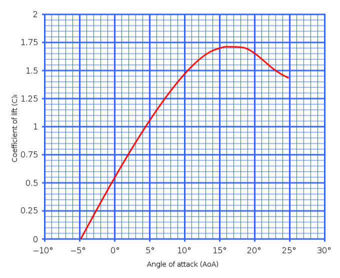
Another variable, ρ (air density), was calculated based on altitude using the following equation.

2. Drag Force
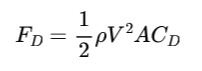
This force, which is quite similar to lift, also has variable parameters. Examples include air density, speed (V), and CD. The formula for calculating the CD parameter is provided below. It essentially consists of two separate components.
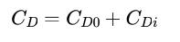
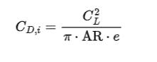
CD0 is referred to as “Parasite Drag” and is defined as a constant value. CDi, on the other hand, is the induced component, which depends on the lift coefficient and calculated by following this formula:
3. Thrust Force
Simple Flight Thrust (Cruise & Climb) has been calculated by following formula when the aircraft is moving. It assumes a standard propeller efficiency of 80%.

4. Weight (Gravity) Force
IIt is the force equivalent to the lift force obtained by multiplying the cosine of the pitch angle by the total weight force (kg × 9.81).
Additional Media
Erasmus+ Internship Project
Task: To examine the thesis “Friction Modeling of Pneumatic Cylinders for Servo-Positioning Systems” by another past master student. To identify areas for improvement in the research and to make improvements in both the theoretical and experimental setup.
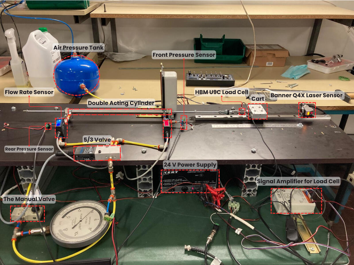
Action: I have worked on 6 different Work-Packages:• State-of-the-art and literature review (2 Weeks)
• Reviewing the thesis data & code (1 Week)
• Developing identification algorithms(2 Week)
• Evaluating identification methods (1 week)
• Sensor calibration & data collection (1 week)
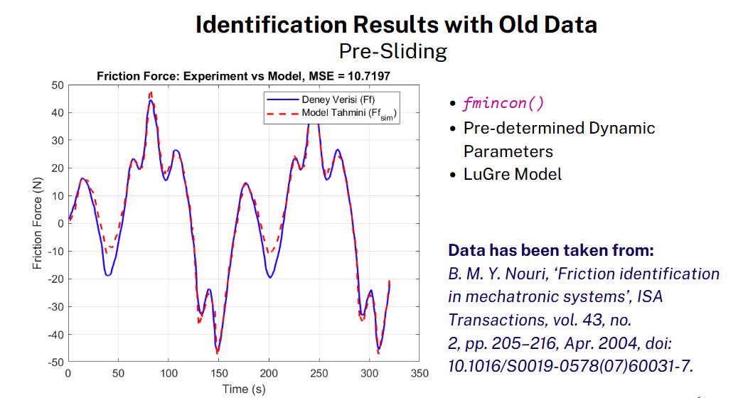
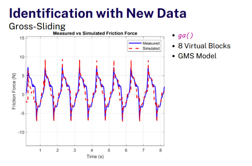
• Performing experiments & preparing final presentation (1 week)Within the scope of the related thesis, it is aimed to understand the friction phenomenon, to determine the models for accurate prediction of friction force and to estimate the parameters in these models with the data obtained from experiments.WP-1: A literature review on friction phenomena was conducted over a period of about two weeks. As a result of this research, appropriate friction models were selected and the concepts on which they are based were understood. A literature review on friction phenomena was conducted over a period of about two weeks. As a result of these investigations, appropriate friction models were selected and the concepts on which they are based were understood. The models to be used were determined as “Generalized Maxwell Model”, “LuGre Model” and finally “Polito Model”.WP-2: In this work package, a reverse engineering approach is adopted and the data processed on MATLAB program, the calculation results obtained by using these data and how the theoretical models are used in MATLAB programming language are learned. Finally, the parts of the research that need to be improved were identified.WP-3: Studies have been initiated on the areas identified as missing or open to improvement in the thesis. For this reason, system identification algorithms have been developed to determine the dynamic and static parameters in the friction models that were previously decided to be used with the help of experimental results.WP-4: In this work package, the developed algorithms were tested with historical data and their performance was evaluated.
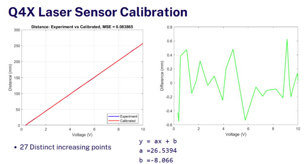
WP-5:After the necessary preliminary preparation and identification methods were determined, the experimental setup was set up in the laboratory. However, in order to obtain reliable results, a laser position sensor was integrated instead of the previously used wired position sensor. Laser sensor and loadcell calibrated before use. The calibration results are reported.
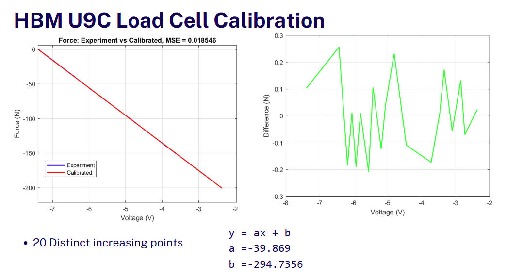
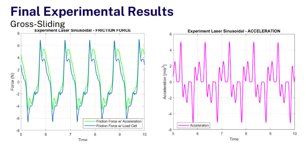
WP-6: Finally, the experimental data obtained with the revised experimental setup were compared with the previous data. Comments were made on the results and system identification methods were tested with new data. The whole study was presented in a presentation to the supervisor.Results: All work packages have been successfully concluded. Missing parts of the research were identified and improved. Improvements in the experimental setup allowed for more reliable data collection. Although no clear conclusions have been reached due to the work time set for the validation of system identification methods, significant progress has been made on the existing thesis. You can view the certificate letter for the supervisor's comments at the end of this section.
IMECH-2
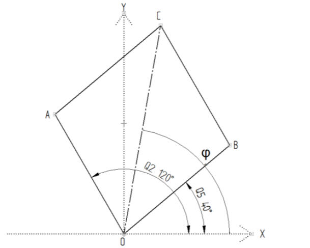
Tasks: The aim of the project is to design and manufacture a uniquely designed multi-purpose 3-DoF parallel manipulator that can provide precise end-effector position data in a Cartesian coordinate system that can be used in teleoperation applications, physical therapy applications and industrial automation applications.Action: I have mainly worked on 3 Work-Packages:WP-1: Performed forward kinematic analysis and inverse kinematic analysis calculations to obtain the end effector position data of the manipulator in the theoretical calculation phase of the project. Converted the obtained calculation into an algorithm via MATLAB to test and verify the relationship between the input angles and the x, y, and z position data of the end effector.
WP-2: I designed the draft model of the project (IMECH-1) using CAD (Autodesk INVENTOR)
software. After verifying that the draft works in a virtual environment, I worked on the mechanical design process of the prototype version (IMECH-2), which will be continued over 7 months. Actively used 3D printers to produce test kits for special parts which have a high tolerance, redesigned failed parts after printing, took an active role in solving design problems in weekly meetings with the project supervisor, purchased necessary machine elements(bolts, nuts, bearings etc.), and perform their assembly. Tracked the weekly tasks inmechanical design and updated them.
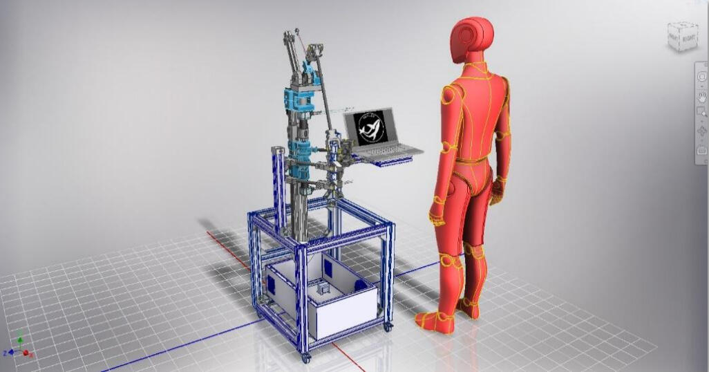
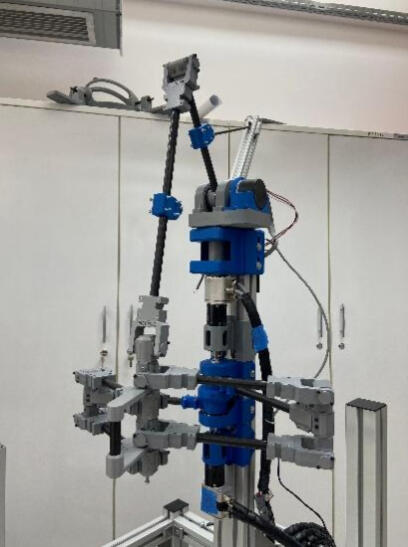
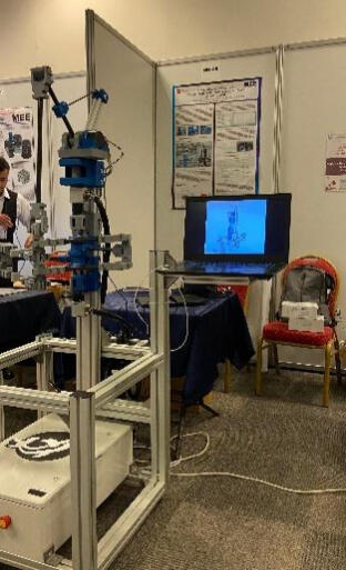
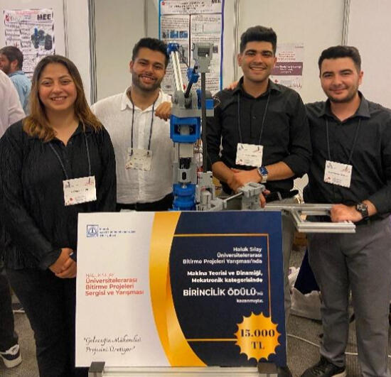
WP-3: Assist in the development and improvement of the SIMULINK control model created using the EPOS2 library, which is downloaded as an integration to MATLAB, to control the Q2, Q5, and Q6 input angles of the MAXON brand EC motors of the manipulator. Integrate forward and inverse kinematic analysis calculations into the SIMULINK environment to observe position and angle information in real-time and participate in testing their accuracy. Lastly, participated in electrical power unit assembly and design. (SIMULINK Control Diagram was not added due to know-how privacy and intellectual property rights.)Results: The project has been successfully designed and produced at the undergraduate level and has achieved its goals. It was supported by TUBITAK and was awarded first place in the competition (see "Awards"). It is still under development and is available for use in the Medical Robotics Laboratory at Izmir Katip Celebi University.
Obtaining Orientation Data with Sensor Fusion
Tasks: Obtaining yaw pitch and roll orientation angles for the product to be developed in the future with the help of the IMU Sensor, transmitting these data wirelessly, reporting the entire progress of the project and storing it in a “readme” file for future use.Action: I have worked on 4 Work-Packages:WP-1: General research on the IMU Sensor and orientation data, conducting initial experiments, finding a suitable algorithm for accurate and stable real-time data collection.
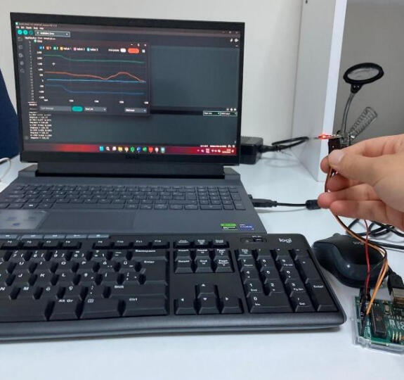
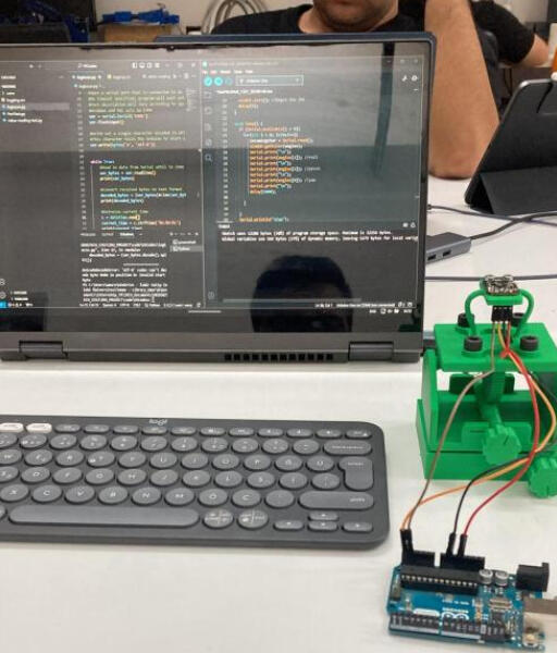
WP-2: Preparing a test setup for collecting and verifying data in a accurate way, testing various algorithms with this setup, reporting and inspecting the results. With the test setup, it is aimed to rotate the sensor in yaw, pitch and roll axes with a gear and screw-like mechanism produced with a 3D printer without human touch.
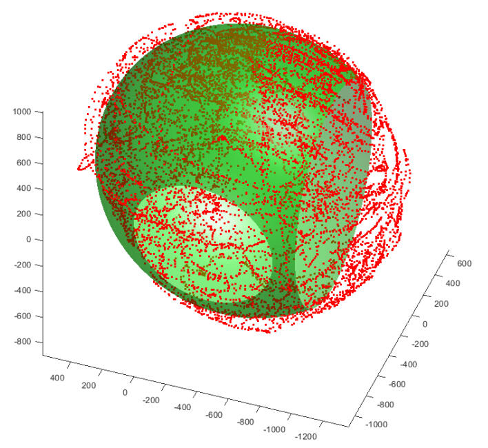
WP-3: Calibration of the gyroscope, magnetometer and pressure sensors on the IMU and verification of the data from these sensors.
WP-4: Development of an algorithm for wireless transmission of IMU acquired and verified data via Wi-Fi and soldering of all electronic components to reduce signal noise.
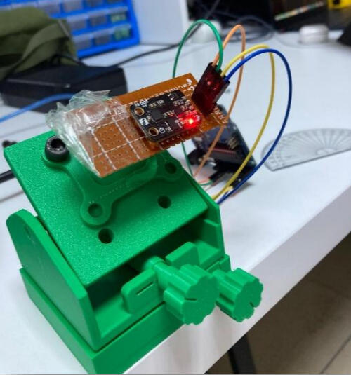
Result: With the IMU provided, healthy data could be collected for all three axes, these data were verified both visually and numerically, and the necessary infrastructure for the project was created. Although there are deficiencies in wireless data transmission due to the end of the internship period, the necessary product foundation for the company has been laid.
PID Position Control of a DC Motor
Tasks: Controlling position of a DC Motor via PIC16F877A.Action: I have worked on 2 Work-Packages:WP-1: Finding an approximated transfer function in the s-domain of a DC motor using the system identification toolbox in MATLAB using sets of input-output data gathered via. DAQ Card. After finding the transfer function, construct a control algorithm and embed it to a soldered from-scratch control card including the PIC16F877F microcontroller.
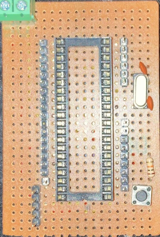
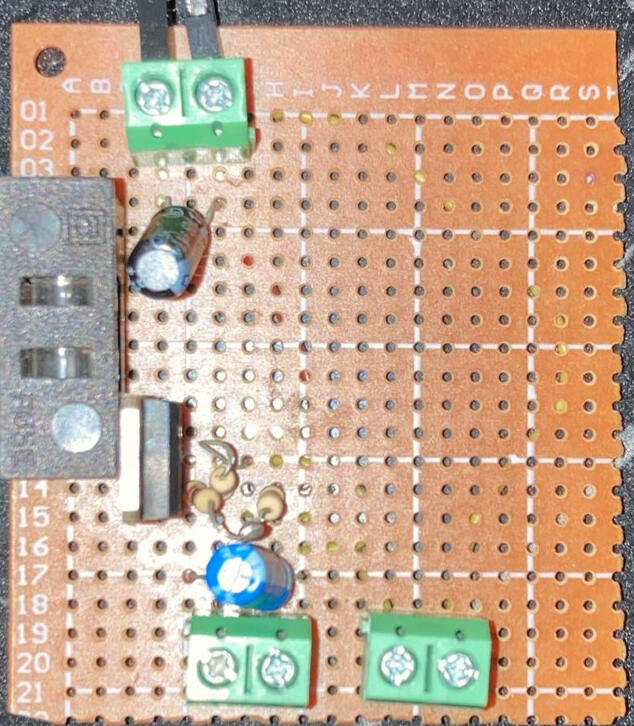
WP-2: Testing the embedded PID algorithm and observing the results.Results: The project was successfully completed, and the motor reached the reference position with sufficient performance using auto-tuned PID parameters.
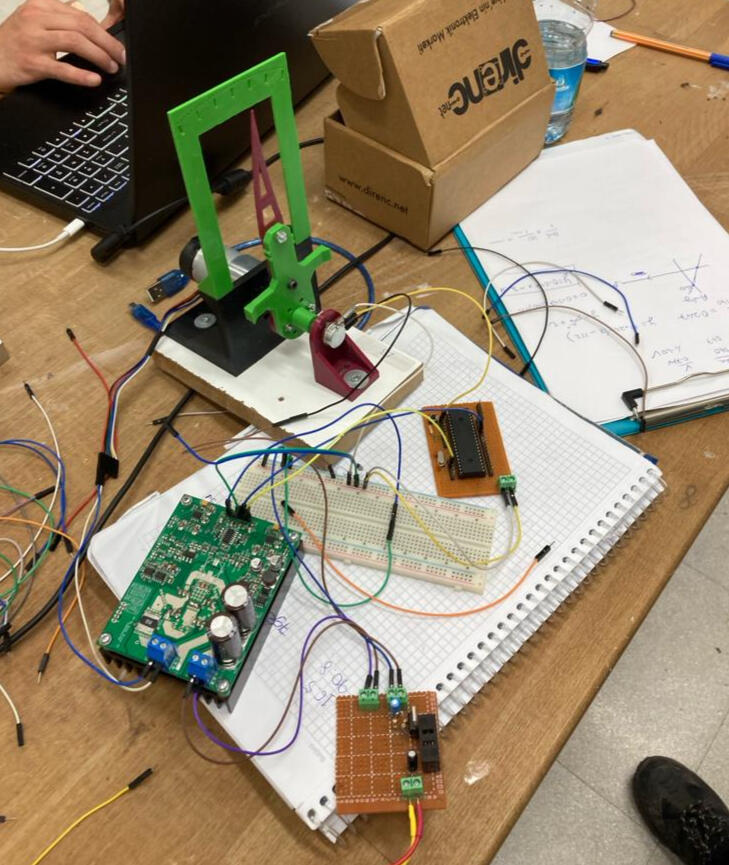
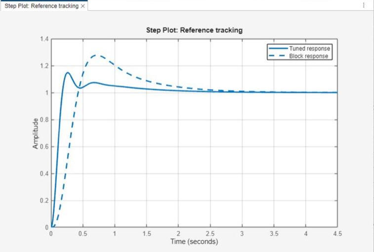
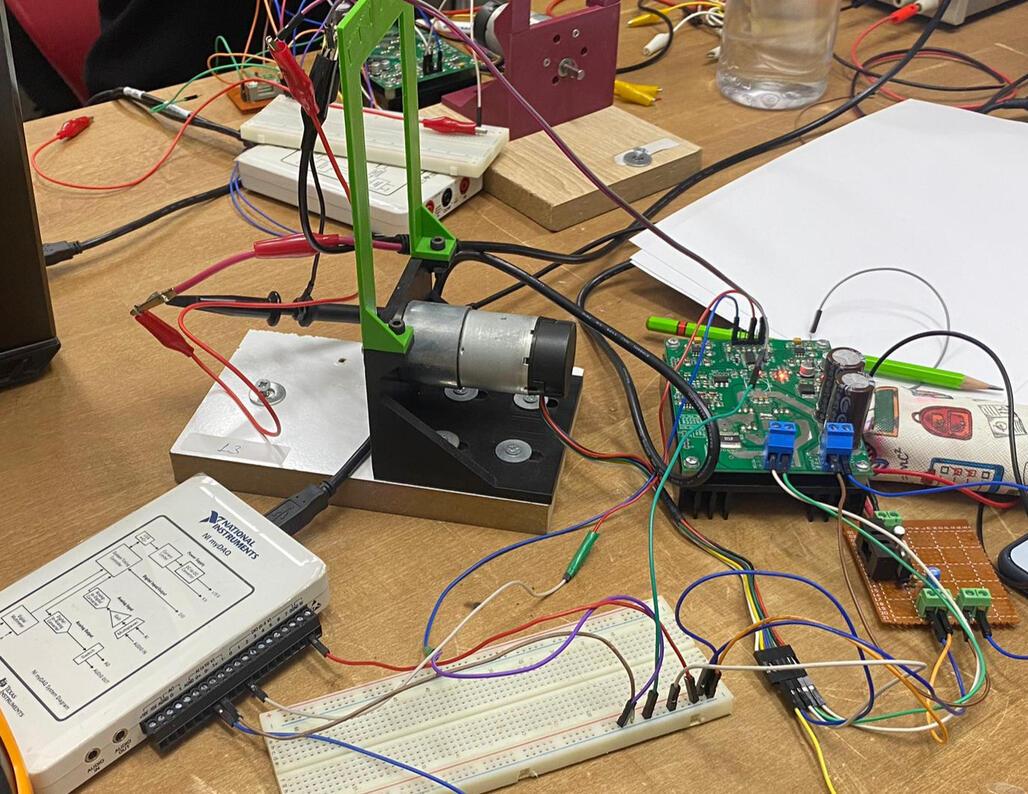
Tasks: Deploy the control model created in SIMULINK to an Arduino for a mechanically pre-produced 2-DoF robotic arm to ensure the end-effector reaches the selected position with the help of a designed MATLAB App UI.Action: I have worked on 2 Work-Packages:WP-1: Resolve existing mechanical issues, secure the mechanism to a platform, and understand its working principles through reverse engineering.WP-2: Design and integrate a digital control algorithm to enable real-time control, calibrate to obtain position data in degrees from a multi-turn potentiometer, and integrate forward and inverse kinematic analysis into the control model.
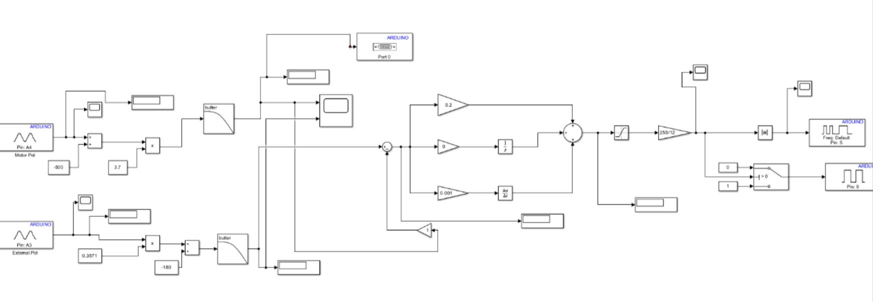
Result: Despite the mechanical problems that were identified and attempted to be resolved within the given timeframe but remained unsolved, the control applications were successfully tested and validated. Experience was gained in digital control, real-time control, and embedded software, even though the mechanism was previously produced by another group of students.